


Global Navigation Satellite Systems (GNSS) are integral to modern navigation, providing position data through a constellation of satellites orbiting the Earth. This article serves as an introduction to the fundamental aspects of GNSS.
Here we discuss the various constellations, provide a brief description of GNSS satellite signals and frequencies, and explain the process by which receivers use these to calculate their position. Additionally, we explore the sources of errors that can affect GNSS accuracy. In the next article, we will examine how corrections can mitigate these errors.
What Are the Different GNSS Constellations?
Global Navigation Satellite System (GNSS) refers to a network of satellites orbiting the Earth that enable receivers to determine their location in three dimensions, as well as time, the fourth dimension. The first and most widely known of these systems, or constellations, is the Global Positioning System (GPS), developed and operated by the United States. Other constellations include Galileo (European Union), BeiDou (China), and GLONASS (Russia).
GNSS Constellations
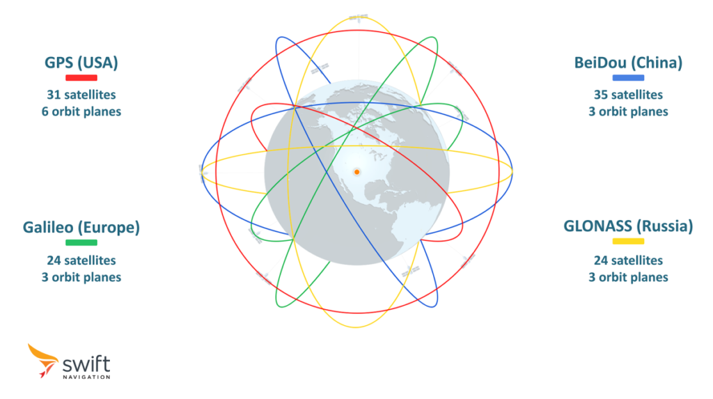
GNSS satellites complete a full revolution around the Earth roughly every 12 hours, traveling around 20,000 km above Earth’s surface, in what’s known as the Medium Earth Orbit (MEO).
Constellations typically aim to maintain at least 24 satellites in orbit, ensuring coverage around the globe and around the clock. Additional satellites are often standing by to ensure reliability.
The last decade has also seen two regional systems taking off:
- Japan’s QZSS, a system that enhances GPS coverage in the Asia-Oceania region currently comprised of four satellites and expanding to seven, then eventually eleven
- India’s NavIC, an eight-satellite independent system that focuses on the subcontinent
How Does GNSS Positioning Work?
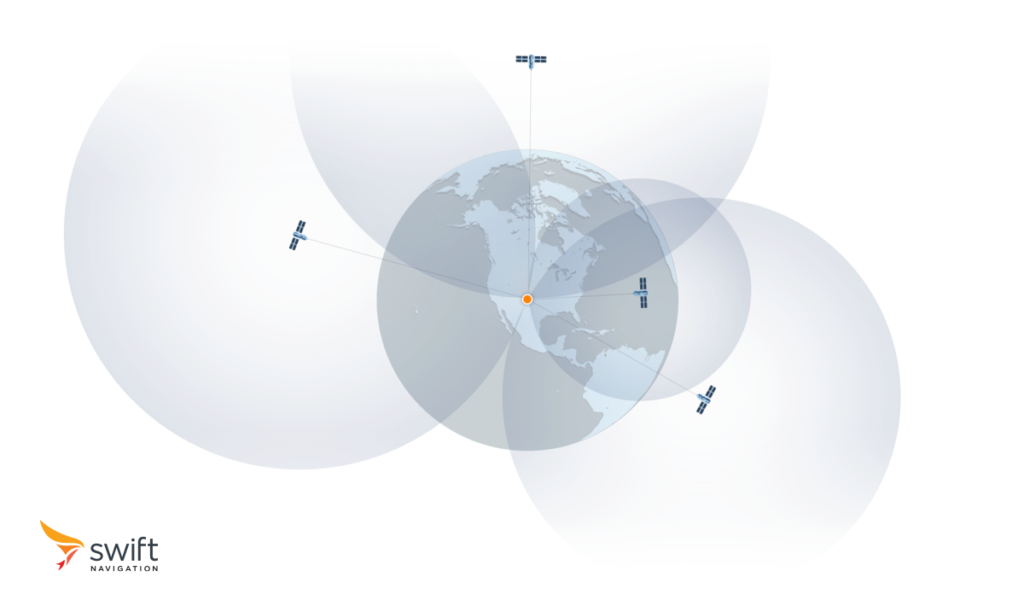
GNSS satellites essentially broadcast where they are located in space (known as ephemeris data) and their associated time (according to their onboard atomic clock). These signals travel at the speed of light and are picked up by the receiver about 70 milliseconds later. Simply put, the receiver infers the exact travel duration by comparing the timestamp from when the message was sent with the current time when it is received. It then uses this time difference to calculate its own distance to the satellite, whose location it knows (distance = time of travel multiplied by speed of light).
Doing this with one satellite places the receiver anywhere on a sphere whose radius is the calculated distance. Doing this simultaneously with three satellites, a process called trilateration, places the rover at the intersection of three spheres, which is a three dimensional point: longitude, latitude, and altitude. As the receiver does not know time accurately enough, a clock error is also estimated by using a fourth satellite and performing multilateration.
These four satellites need to be from the same constellation as each system has its own time reference. This is why constellations are designed to ensure that at least four of its satellites are visible from any point on Earth at any given time. Many GNSS receivers can combine measurements from multiple constellations, improving their accuracy and resilience in areas with obstructed sky views or challenging environmental conditions.
Multilateration
What Constitutes GNSS Signals?
GNSS signals comprise three fundamental components: the navigation message, the code, and their carrier.
The navigation message contains the information about the satellite orbit and a timestamp which allows the receiver to understand the unambiguous absolute time used by the constellation. It is not present on all signals, as it can affect the time it takes a receiver to acquire and track a signal. Signals not containing this information are referred to as pilot signals.
The code, or pseudorandom noise (PRN), is a unique identifier transmitted by each GNSS satellite. By comparing, or correlating, the received signal with known PRN codes, a receiver can determine which satellite it is tracking, as well as the time it took for the signal to reach it. These two pieces of information allow the receiver to derive its own distance from the satellite, known as the pseudorange, as described in the previous section.
Coarse/Acquisition (C/A) code and the Precise (P) code are examples of such codes in the GPS system. C/A code has a chipping rate of 1.023 MHz and is used for civilian applications, while P code, with its much higher chipping rate of 10.23 MHz, offers higher accuracy and is encrypted for military use.
The carrier is the continuous sinusoidal waveform that carries the code signal. Its frequency ranges from 1164 to 1610 MHz, which resides in the L-Band radio spectrum.
What Are the Different L-Bands Used by GNSS?
The L-Band is divided into three primary bands: L1, L2, and L5. Each band serves specific purposes within the GNSS architecture, offering distinct benefits for positioning, navigation, and timing applications.
| Band | Center Frequency | Description |
|---|---|---|
| L1 | 1575 MHz | First to have been used and is fundamental for civilian GNSS services. Carries the C/A code used for acquiring satellite data, calculating position fixes, and providing accurate timing information. |
| L2 | 1227 MHz | Supports higher precision applications by providing additional ranging and carrier signals. Operating at a lower frequency, enhances accuracy and integrity of positioning solutions, especially in challenging environments that attenuate signal strength such as under foliage or harsh weather. |
| L5 | 1176 MHz | Recent addition to the L-Band spectrum, designed to offer improved accuracy, integrity, and robustness for safety-critical applications. At an even lower frequency than L2, further enhances the resilience of GNSS positioning solutions, particularly in aviation, maritime, and land-based applications where high accuracy and reliability are paramount. |
Almost all receivers use L1 as their primary frequency band as it is supported by all GNSS satellites, thus ensuring high availability and fast signal acquisition. As constellations upgrade their satellites to support L2 and L5, many receivers increasingly leverage these additional bands to improve reliability and accuracy, giving rise to dual-, triple-, and even quad-band receivers.
GNSS Frequency Bands

What Are the Common Sources of GNSS Errors?
GNSS systems are susceptible to various sources of errors that degrade the accuracy of positioning solutions.
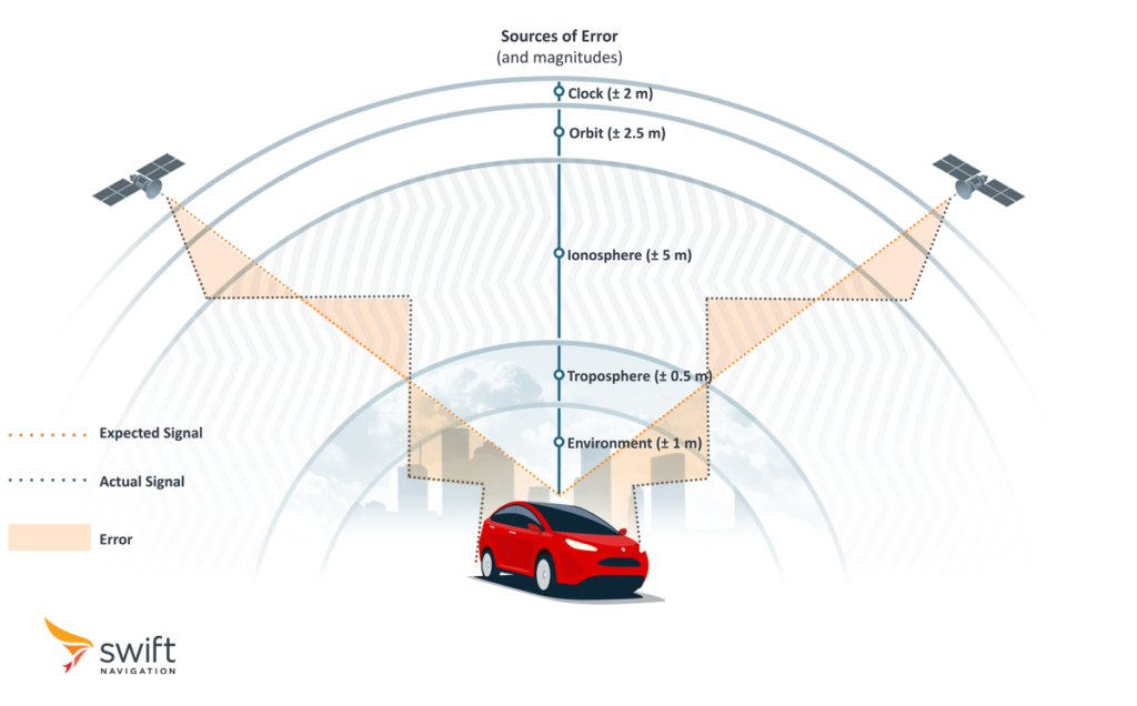
We mentioned earlier that signals travel at the speed of light. That is true in a vacuum. Once these signals enter Earth’s atmosphere, they slow down because of their interaction with the ionosphere and troposphere’s ionized particles. Since measuring pseudoranges is a distance calculation using time of travel and signal speed, delays directly impact accuracy.
Additional sources of errors include inaccuracies in the data describing satellites’ orbits, miscalibration of their onboard clocks, as well as imperfections within the GNSS receivers themselves.
Below is a summary of different types of common errors, whose cumulative outcome results in a positioning error of the order of 5 to 10 meters.
| Type of Error | Description | Range |
|---|---|---|
| Satellite Clock | Even the most precise atomic clocks aboard GNSS satellites can experience slight deviations, each nanosecond leading to a 0.3 m positioning error. | ± 2 m |
| Satellite Orbit | Uncertainties in the predicted satellite orbits introduce deviations between the actual and expected satellite positions. | ± 2.5 m |
| Ionosphere | Earth’s ionosphere bends and reflects GNSS signals, affecting their effective speed and impacting the accuracy of distance measurements. Delays are inversely proportional to the square of the signal frequency, so the lower the frequency, the longer the delay. | ± 5 m |
| Troposphere | Closer to the surface, the troposphere’s refraction and humidity further distort signal propagation, contributing to position errors, particularly in elevation measurements. Delays in the troposphere are independent of signal frequency. | ± 0.5 m |
| Environment | Signals reflecting off surfaces such as buildings, terrain, or water can reach the receiver slightly later than direct signals, leading to errors in distance measurements. | ± 1 m |
| Receiver Noise and Bias | Inside the receiver, noise in signal processing circuits and biases in measurement algorithms can introduce errors into positioning solutions. | ± 0.3 m |
GNSS Sources of Errors
How to Improve GNSS Precision?
In our preceding discussion, we explored the diverse sources of errors that can impact GNSS signals, ranging from satellite clock and orbit errors to atmospheric delays. To counteract these inaccuracies and elevate the precision of GNSS positioning, a suite of correction methods has evolved over the past three decades. In this section, we delve into the influence of different measurement methods on precision and convergence time, followed by an examination of the two fundamental strategies employed to rectify errors: the differenced and modeled approaches.
What Are the GNSS Measurement Types
Measurement types are fundamental to determining the positioning accuracy and the method’s applicability. Two primary types of measurements are used: code-based and carrier-phase measurements.
As discussed earlier, code-based measurements rely on the pseudorandom noise (PRN) code transmitted by GNSS satellites to determine the time it takes for the signal to travel from the satellite to the receiver. With a low chipping rate, such as 1.023 MHz for the GPS C/A code, these measurements yield wavelengths on the order of 300 meters, translating to a relatively coarse accuracy of several meters.
Conversely, carrier-phase measurements track the phase of the high-frequency carrier wave modulating the PRN code, typically between 1100 MHz and 1600 MHz. With much shorter wavelengths, such as 19 cm for GPS L1, carrier-phase measurements offer significantly finer resolution, achieving millimeter-level accuracy. However, they entail resolving the integer ambiguity, the unknown number of complete wavelengths traversed by the signal, rendering the processing more complex and elongating convergence time compared to the code-based technique.
What Are the Different GNSS Correction Types?
The main strategies for enhancing positioning accuracy are the differenced and modeled approaches.
Differenced corrections involve comparing the GNSS measurements from a ground reference station at a known location with those from a mobile receiver, or rover, whose position is being determined.
At the outset, a reference station is established at a fixed location with meticulously surveyed coordinates. It continuously receives signals from GNSS satellites, computing its presumed location and deriving the difference with its known location. This difference encapsulates the errors affecting the reference station’s measurements, which happen to be very similar to those affecting rovers in its vicinity. Transmitted in real-time to the rover, typically by the reference station itself, this discrepancy eradicates systematic errors influencing its measurements, substantially enhancing positioning accuracy.
Modeled corrections leverage mathematical models to estimate and rectify various sources of error affecting satellite signals.
Fundamentally, this method revolves around crafting sophisticated mathematical models depicting the behavior of error sources, including ionospheric and tropospheric delays, satellite orbit inaccuracies, and clock biases. These models account for factors such as satellite geometry, atmospheric conditions, and the Earth’s gravitational field. Continuously refined with updated data, these estimates serve as the foundation for generating correction values for each satellite signal. Applied to the raw measurements obtained by the receiver, these correction values refine its positioning solution, yielding higher accuracy.
In the next article, we will apply these concepts while exploring some of the primary GNSS correction techniques – SBAS, DGNSS, PPP, RTK, and PPP-RTK – and examine their trade-offs in terms of accuracy, coverage, power consumption, reliability, and cost.